
Simple and Repeatable
October 7, 2020 | By John Siegenthaler
Finding a simple and repeatable way to manage heat input to a hydronic space heating distribution system from both a renewable and an auxiliary heat source.
Over the last 40 years I’ve had the opportunity to work with several types of renewable energy heat sources including solar thermal collectors, cordwood boilers, wood pellet boilers and heat pumps. They can all be integrated with hydronic heating distribution systems.
I’ve also worked with systems that took advantage of time-of-use electrical rates. or “off-peak” rates. During specific times of day, usually at night, and sometimes specific dates (e.g., weekday, weekend, holiday, etc.) the cost of purchasing electricity from the local utility is deeply discounted. Utilities do this to help manage peak demand by incentivizing the purchase of electricity at times of low demand.
So what do renewable energy heat sources and time-of-use electrical rates have in common? The answer is that systems using these energy sources almost always require significant thermal storage. For hydronic applications that storage consists of a large insulated tank filled with water.
Tankage
Thermal storage tanks can be categorized as unpressurized and pressurized. Unpressurized thermal storage tanks must be vented to the atmosphere, usually through a small opening. This ensures that the pressure at the water’s upper surface cannot increase.
These tanks usually consist of an open-top insulated structural shell that’s assembled on site. A flexible liner made of EPDM rubber or polypropylene is placed into this shell, similar to how a trash bag fits into a trash can. The liner contains the water. An insulated lid goes over the top. Piping penetrations are usually made just above the highest water level in the tank.
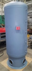
Figure 1 – pressurized thermal storage tank.
A pressurized thermal storage tank, such as the 350-gallon tank shown in Figure 1 (left), are usually constructed of steel. They can be insulated using several types of materials. That insulation is usually installed after the tank has been piped and all connections to the tank have been pressure tested.
Most mechanical codes require pressurized tanks larger than 119 US gallons to be ASME certified. This process involves traceable materials and physical inspections during fabrication. It adds assurance that the tank is well built and safe, when applied within the certification limits. It also adds significant cost to the units.
Priorities
Systems using a thermal storage tank heated by a renewable source or off-peak electricity usually have an auxiliary heat source. In retrofit applications that auxiliary heat source is often an existing boiler. In new systems it could also be a boiler or a heat pump.
The control concept is to use heat from thermal storage whenever possible, and only use the auxiliary heat source when necessary to ensure the building remains comfortable.
Heat is transferred from thermal storage into a heating distribution system as needed. Figure 2 (below) shows a simple way to do this using a pair of closely spaced tees that provide hydraulic separation between the tank circulator (P2 , bottom right) and the distribution circulator (P3, top left).
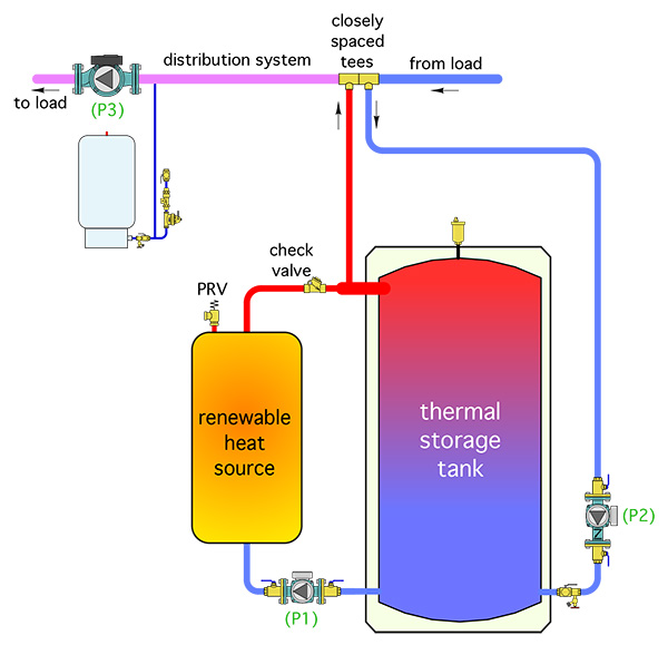
Figure 2.
Circulator (P2) in Figure 2 could be controlled as an on/off device, or as a variable speed injection pump. The latter allows accurate control of the water temperature sent to the space heating load. It also allows for outdoor reset of that supply water temperature.
Figure 3 (below) shows how an auxiliary heat source would be integrated into this piping arrangement. Another set of closely spaced tees connects the auxiliary heat source to the distribution system. These tees provide hydraulic separation between circulator (P4) and the distribution circulator (P3).
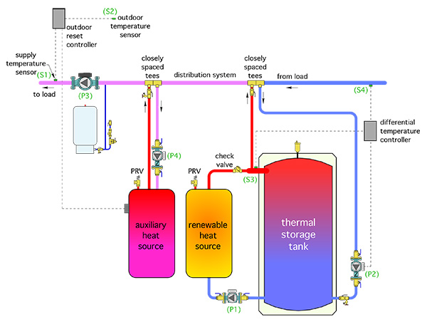
Figure 3.
The auxiliary heat source also connects “downstream” of the thermal storage tank. This allows the coolest water in the system, that returning from the load, to flow into the lower tank connection. This enables the renewable energy heat source to operate at the lowest temperatures the system can provide. Lower water temperature operation increases the efficiency of most renewable energy heat sources.
Control Concept
The auxiliary heat source is only turned on when there is a demand from the space heating load, and when the temperature of the water supplied to the load drops slightly below the minimum value necessary to maintain the heating load, as determined by an outdoor reset controller.
In systems with this configuration (e.g., thermal storage heated by a renewable heat source, along with an auxiliary heat source) it’s important not to allow heat produced by the auxiliary heat source to inadvertently enter the thermal storage tank.
Doing so would allow high grade energy such as gas, propane, fuel oil or electricity to be converted to lower grade energy (e.g., heat) before that energy is needed by the load. Heat is much harder to store compared to keeping energy in high grade form until needed.
The key to preventing inadvertent transfer of heat produced by the auxiliary heat source into thermal storage is by comparing the temperature of the water returning from the distribution system to that at the upper header of the thermal storage tank.
As long as the temperature at the upper tank header is a few degrees higher than the temperature of water returning from the distribution system, the thermal storage tank, or the renewable heat source that supplies it, can make a positive energy contribution to the space heating load. This control function is easily handled using a differential temperature controller.
Figure 3 (above) also shows a differential temperature controller installed to compare the temperature at the return side of the distribution system (S4) to the temperature at the upper tank header (S3). Circulator (P2) is only allowed to start if the temperature at sensor (S3) is at least 5-degrees F above the temperature at sensor (S4).
This prevents heat generated by the auxiliary heat source from being inadvertently sent into thermal storage. It also prevents flow from what might be cool thermal storage into the distribution system. If the temperature at sensor (S3) subsequently drops to within 3-degrees F of the temperature at sensor (S4), circulator (P2) is turned off. The on/off temperature differentials of 5F and 3F are only suggested values. To minimize sensing error it’s best to use identical mounting techniques for both sensors.
Outdoor Reset
Figure 4 (below) shows the simple wiring needed to combine the functions of the outdoor reset controller with the differential temperature controller.
For the wiring shown, the controllers are turned on only when there is a demand for heat from the load. Both are assumed to be powered by 24 VAC.
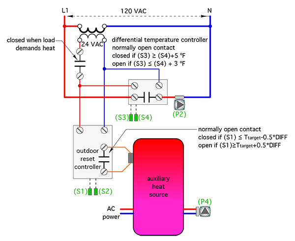
Figure 4.
When the normally open contact in the differential temperature controller closes it passes line voltage to operate circulator (P2). When the normally open contact in the outdoor reset controller closes it signals the auxiliary heat source to operate. That heat source is shown as being supplied from a separate electrical source. Circulator (P4) is powered through that same electrical source and operates whenever the auxiliary heat source is on.
The controllers shown are readily available and are relatively inexpensive. The control functions they provide are well established over several decades. The combined functionality of these two controllers provides a simple and repeatable way to manage heat input to a space heating distribution system from both a renewable heat source, (or heat stored from off-peak electricity), and an auxiliary heat source. <>

John Siegenthaler, P.E.

